Ads are chosen by Google and not necessarily endorsed by this website.
|
|||||||
|
|||||||
Precision AR10 Build |
|
It's true that AR15's are like LEGOs for adults. They are simple to assemble with nothing more than hand tools and the options are almost limitless. I have built several in my time and enjoyed the outcome. However the AR15 is limited in the amount of powder it can burn and lead it can sling. Sometimes it just takes a bigger hammer to do the job. Since I had a bit of a background in assembling AR15s I figured why not an AR10? First off, lets clear up some confusion about the AR10. The AR10 is a trademark of Armalite. Many people have taken to calling any .308 AR an AR10. This is incorrect for many reasons beyond the legal issues. First and foremost parts will not readily interchange between .308 ARs. Magazines are also an issue. With AR15s you can interchange most any part with little regard for manufacturer. Confusion abounds when someone tells me that they are having a problem with their AR10 only to find out that they don't have an AR10. They may instead be talking about their DPMS LR-308 or RRA LAR-8. |
 |
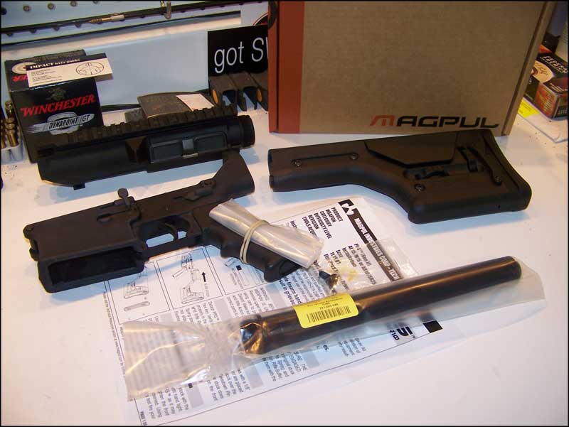
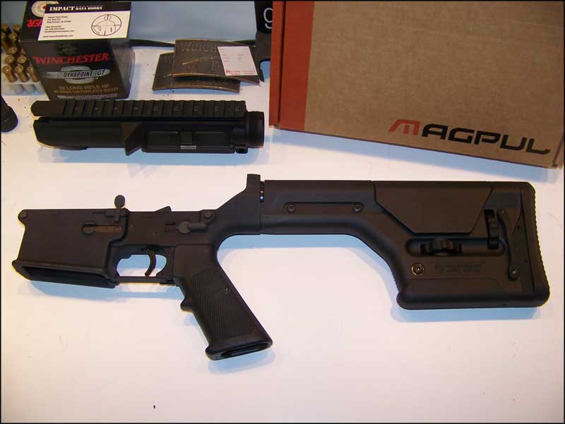
For the purposes of this series we will be starting with a complete "Eagle Arms" (by Armalite) AR-10 lower, sans buttstock. I purchased this lower pre-election before the prices spiked and stashed it away hoping to build it out later. I chose the assembled lower because at the time it was cheaper than purchasing a stripped lower and a parts kit. The lower comes with Armalite's Tactical Two Stage trigger installed. This is a bit heavy to be considered a "match" trigger, but it's acceptable for a duty gun. This rifle will be a precision build and a test bed for some later articles. The first part of this series will be the installation of the Magpul PRS (Precision Rifle Stock). This stock has two properties that make it an excellent candidate for our build. The first is it's weight. The PRS is probably the heaviest AR stock available. This weight hanging on the back of the rifle will help in offsetting the 21" Noveske barrel that we will be screwing into the front. The second benefit is that it's adjustable for height of comb and length of pull. This will allow the rifle to be quickly fitted to students without any tape or foam mats being harmed in the process. When shopping for a PRS ensure you select the correct model. Magpul produces one model intended for the AR15 and one for the AR10/SR25 series of rifles. The difference is that the cheek riser is set further back on the AR10 version. This allows for the charging handle to move fully to the rear. The AR10 version can be used on the AR15, but not the reverse. The second part is the installation of a Magpul MOE Grip. Due to my hand and finger sizing the standard A2 pistol grip that comes with the Assembled Lower places my hand too far forward for correct trigger finger placement. When the MIAD was first released I purchased one for an AR15 project. When the MOE Grip was later released I found that the configuration I chose for the MIAD was almost exactly the same as the MOE. From that point on all the grips I have ordered have been MOE Grips. The third part of the series will be the installation of a Noveske 21" barrel and Badger Stabilizer Handguard. Part 1 - Part 2 - Part 3 - Part 4 |
|
|
To install the Magpul PRS you will need the following: |
|
|
|
Start by making sure your receiver threads are clean and free of burrs. Then start the Receiver Extension into the receiver. |
 |
 |
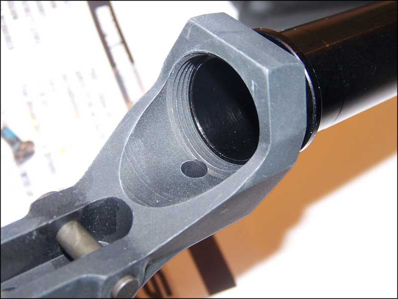
Continue to screw it into the receiver until it is even with the Buffer Detent Hole. |
| Locate your Buffer Detent and Buffer Detent Spring. If you purchased your lower as an assembled piece, then these components should have been contained inside a plastic bag, rubber banded to the pistol grip. |  |
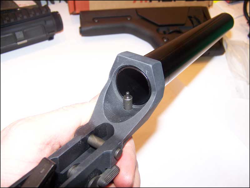 |
Insert the Buffer Detent and Spring into the Receiver. |
| Press Down the Buffer Detent. | 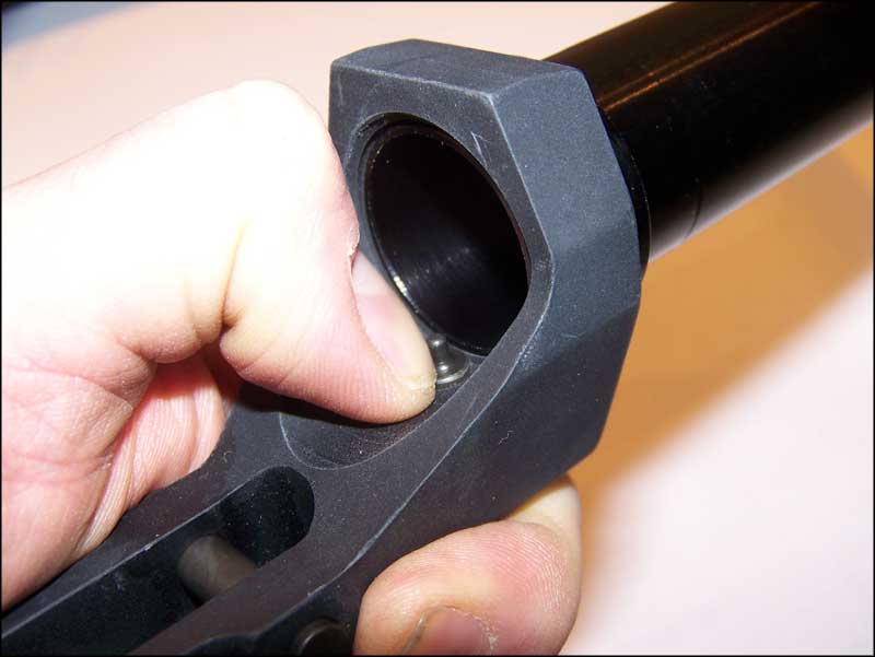 |
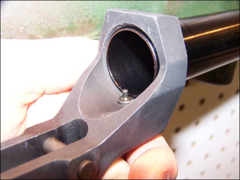 |
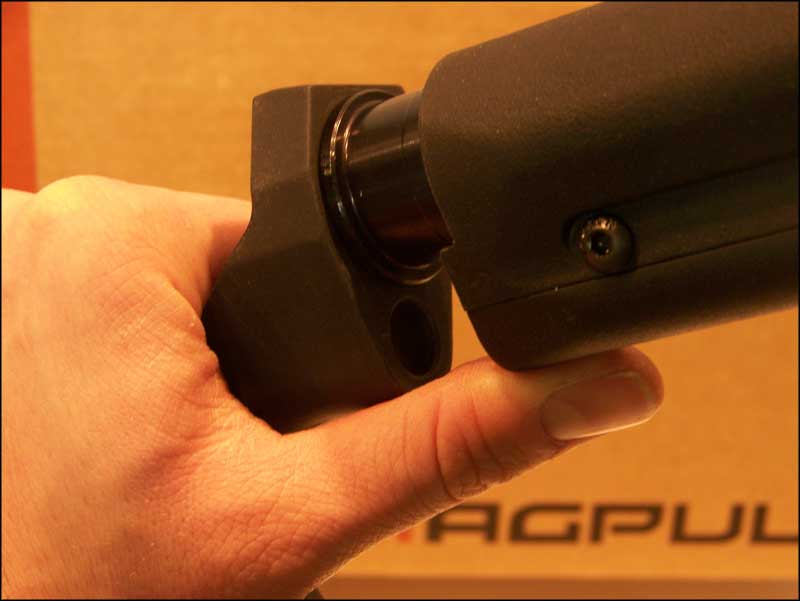
Screw the Receiver Extension into the Receiver until the shoulder stops against the back of the Receiver. The Receiver Extension should protrude far enough into the Receiver to retain the Buffer Detent. If the Receiver Extension contacts the pin of the Buffer Detent before it bottoms out against the back of the Receiver, then you will need to file away some of the edge of the Receiver Extension. |
| Remove your PRS from the package and make sure no debris remains in the hole for the Receiver Extension. | 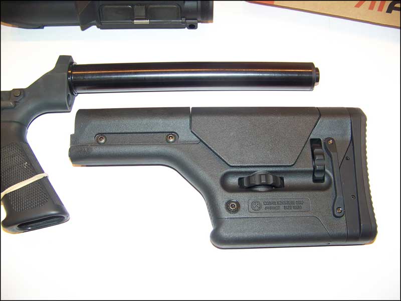 |
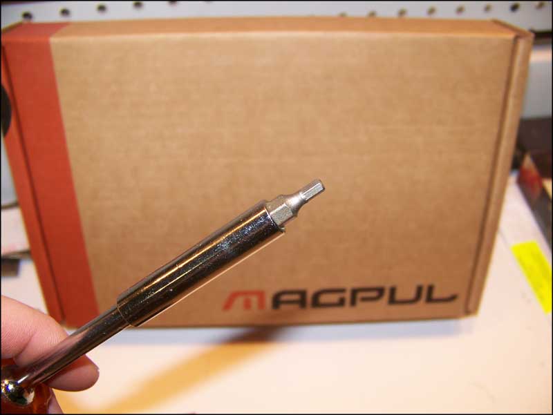 |
Locate your 1/8" Hex Key or Driver. |
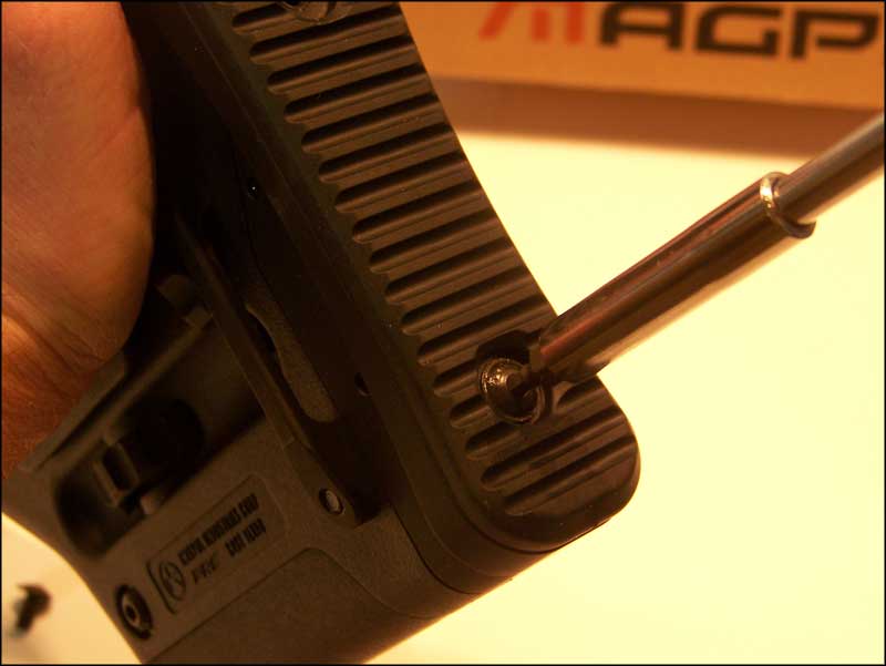
| Remove both screws retaining the rubber Butt-Pad. | 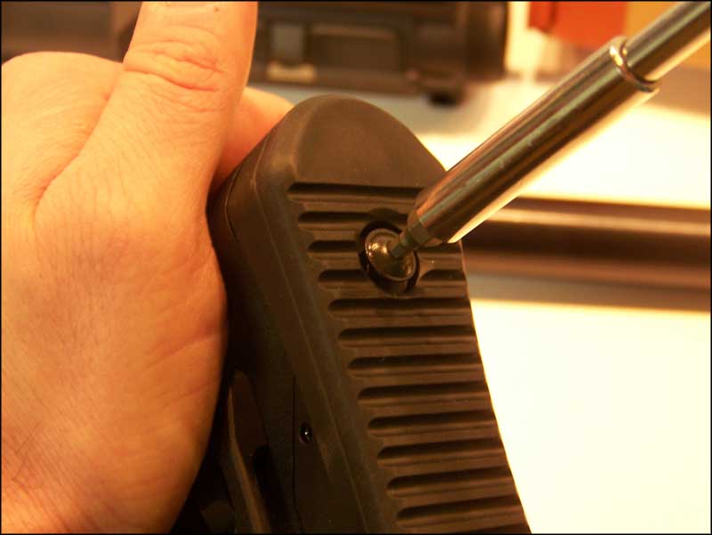 |
 |
Pop off the rubber Butt-Pad. |
Slide the PRS on to the Receiver Extension. Make sure it fits flush against the receiver. If the stock does not slide on easily, then loosen the two "Footman's Loop" (Sling Mount) screws using your 1/8" hex driver or key. |
 |
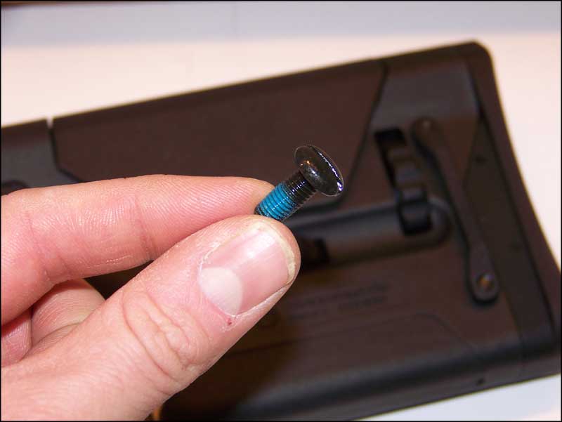 |
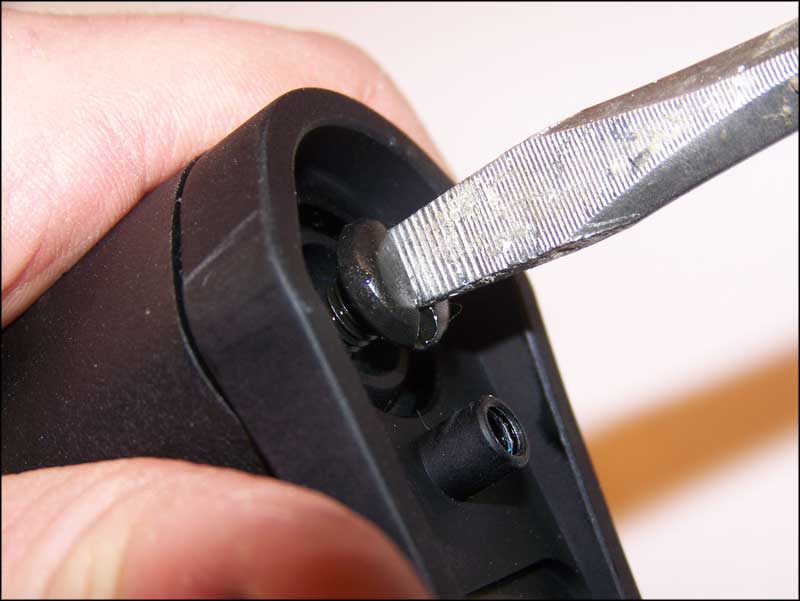
Locate the Vented Mounting Screw provided with your PRS. Note that it is already coated with thread locker so no extra is required. DO NOT use any other screw to attach the stock. This could cause damage to the stock or it could cause a malfunction when firing the weapon. |
Install the screw and tighten to hand tight. If you loosened the Footman's Loop screws, re-tighten them. |
 |
 |
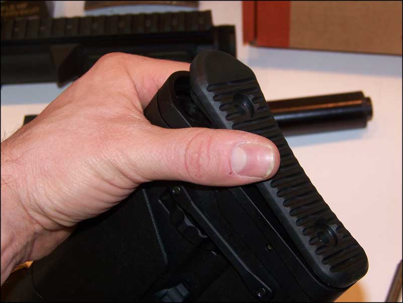
Reinstall the rubber Butt-pad. |
Install the Operating Spring onto the Buffer. Ensure that the hammer is in the cocked position and that the selector is in the "SAFE" position. Then insert the Buffer and Spring into the Receiver Extension tube. Your Installation is now complete. |
 |
|
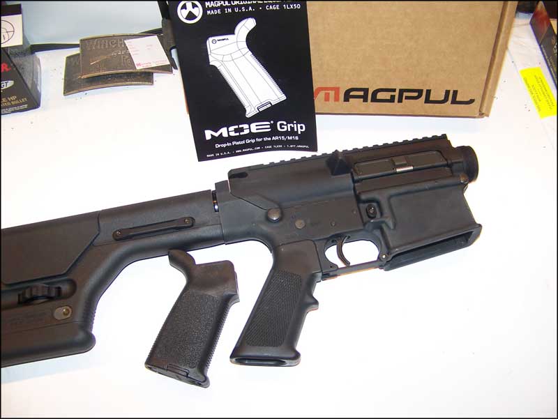
To install the Magpul MOE Grip you will need the following: |
|
|
|
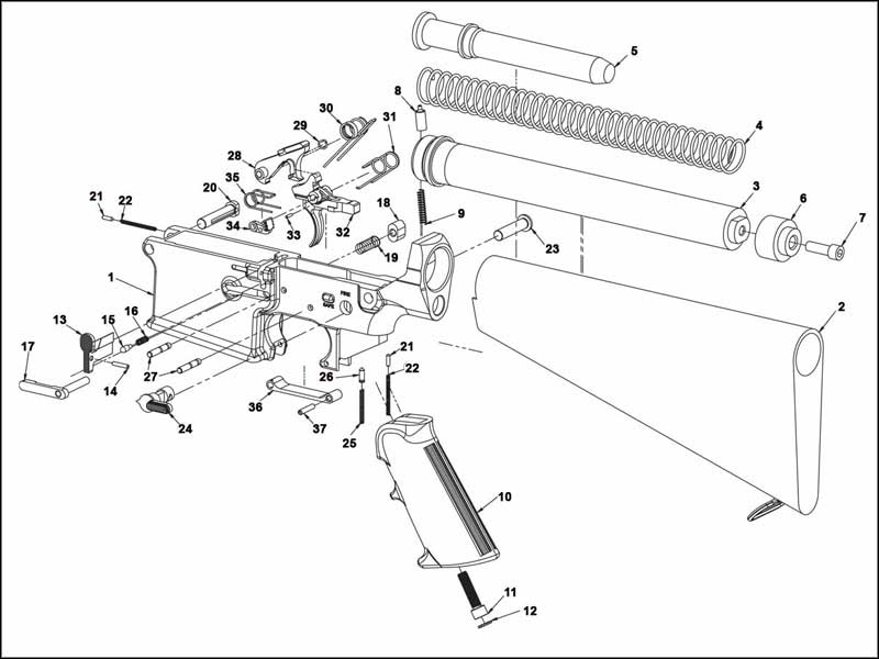
| Locate a 3/16" Hex Key or Hex Driver. Rotate your receiver upside down so that your pistol grip is pointed upward. Loosen the screw retaining the grip. |  |
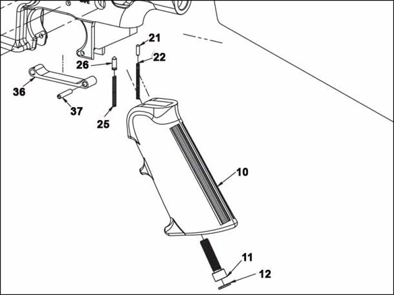 |
On the AR15 the pistol grip only retains the selector detent and spring. The AR10 design also uses this feature, but also uses the pistol grip to retain the takedown pin detent and spring on the opposite side. Please reference the diagram on left. When you remove the pistol grip from your receiver, take care to keep the receiver upside down so that you don't loose the detents or springs. |
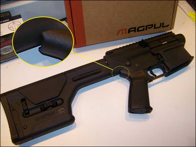
Remove the trap door from the MOE Grip and install it in the same way you removed the stock A2 grip. You will note that with the MOE or even with the MIAD with back straps there will be a small gap between the grip and receiver. This is not an issue for function, but if it bothers you, Magpul makes a filler insert for the MIAD. To use it with the MOE you will need to do some modification. |
 |
Part 3 - Noveske Barrel and Badger Stabilizer Install
To install the barrel and stabilizer you will need the following: |
|
|
|
|
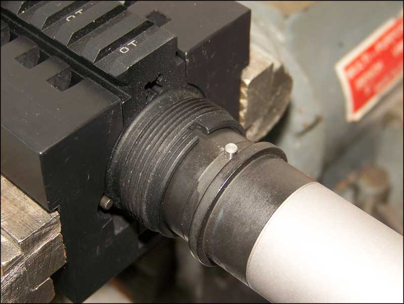
| For this installation we will be using a "clamshell" type action block from Bushmaster. This block almost perfectly fits the Armalite upper receiver. The only problem will be the "hump" on the left side of the receiver. This is larger than the cutout in the block. As a result, when you clamp the block down for the first time, it will most likely break out two of the "fingers" along the top of the block. This is not a problem and should be viewed at the block "self-adjusting" to fit your upper. It doesn't not affect function in the least. | 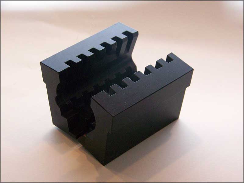 |
|
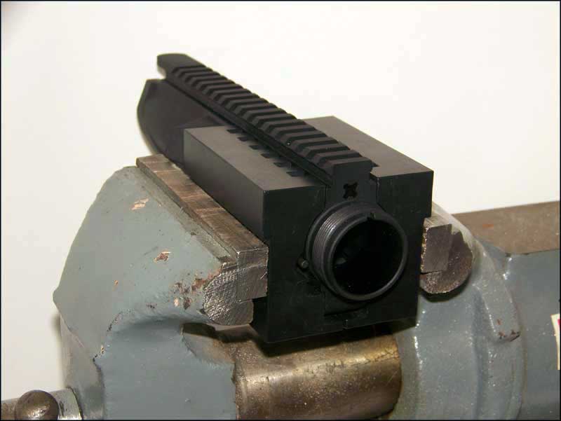 |
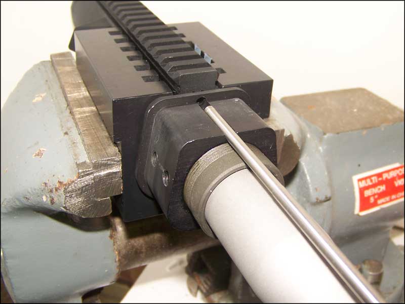
Set the receiver in the block and clamp it into a heavy bench vise. Make sure the face of the block is even with the edge of your vise. Otherwise you will have clearance issues when attempting to install the barrel nut. Also take care that the case deflector on the receiver does not contact the jaws of the vice. We had to clamp the block just a little bit below the "ledge" machined into it to prevent damage to the case deflector. |
|
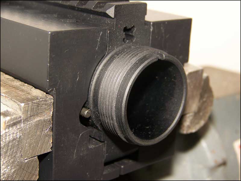
Inspect the threads on the receiver for any nicks or burrs. If you have any, spin the barrel nut on to see if they can be knocked down. If they cause any resistance, you may need to dress them with a file. Go slow, aluminum cuts quickly. Make sure the mouth of the receiver is clean and free of defects. |
 |
|
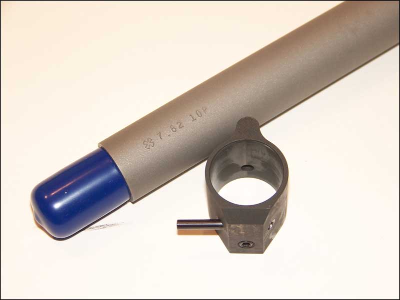 |
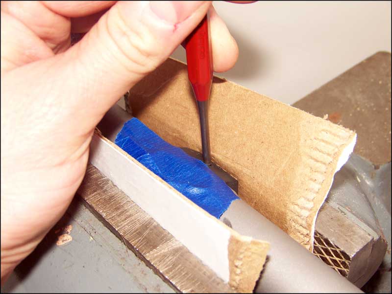
If you purchase a Noveske 7.62 barrel it will come with the gas block attached. I HIGHLY suggest you ask Noveske to ship the barrel with the gas block removed. They can be a real pain to remove especially if you don't have a heavy bench vise. Since much cussing and three hands were a requirement to remove the gas block, I did not take any pictured of the process. I shot the pin with some penetrating oil the day before. I then noted the direction the pin was driven in. A quick call to Noveske confirmed that it is a straight pin NOT a taper pin. It does not matter which way you drive it out. I just prefer to push it out the same way it went in. Remove the set screw from the bottom of the block. Using some cardboard, clamp the barrel by the gas block in your vise. Using the appropriate sized punch and a large hammer, drive the pin out. Do not try to use too small of a punch and do not try to "tap" the pin out. It takes quite a bit of force to get it out. Use some tape to protect the gas block finish from a slip of the punch. It will happen and we have a couple of scratches to prove it. |
|
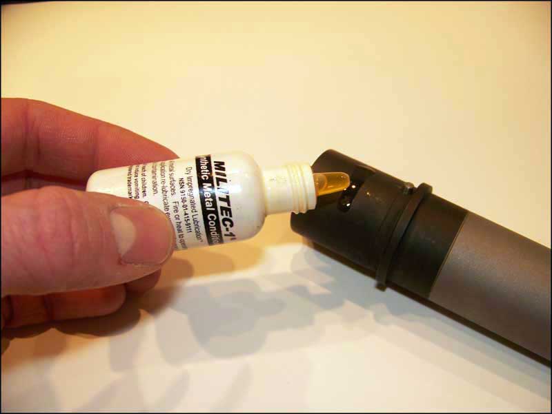
Since this will be a hard use rifle, it will get subjected to wet-weather use. To this end I like to add a little protectant to the outside of the barrel extension. This is not necessary, but even finished metal likes to rust. The oil will cook off when we get it heated up, but the Militec-1 should leave some protective qualities even after it's gone. |
 |
|
 |
Slide the barrel into the receiver. Align the pin on the extension with the notch on the receiver. |
|
| Seat the barrel fully into the receiver. Make sure the shoulder on the extension seats tightly against the receiver. If there is any gap on either side of the pin, you will need to make sure the barrel is indexed properly and then peen the notch to hold the pin snugly. | 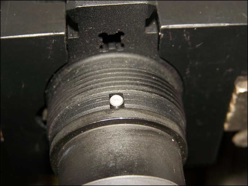 |
|
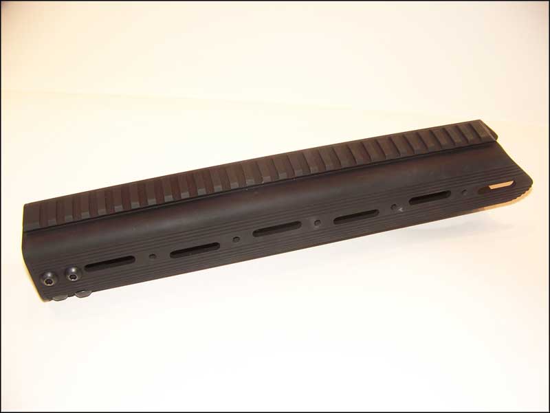 |
The Badger Stabilizer is a one piece extruded handguard with an integral top rail. Smaller rail section scan be added to the sides or bottom. The Stabilizer comes with two sling studs mounted on the bottom. These studs can be removed if you choose to install a bottom rail. |
| To start the installation you will need to remove the eight hex head screws securing the mounting block to the handguard. |  |
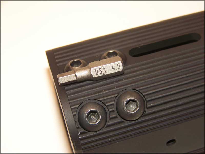 |
You will need a 4mm hex driver. |
The handguard consists of the outer tube, Mounting Block, Barrel Nut and eight screws. |
 |
 |
Installing the Stabilizer will require a high quality grease. My grease of choice for AR barrel nuts is Coastal Moly Grease. It comes in a tub from the auto parts store for a couple bucks. More than likely this will last you for a lifetime of barrel installs. |
| Smear some grease on the threads of the receiver. | 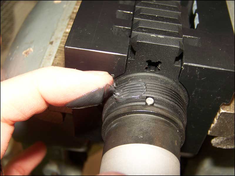 |
 |
Smear a small bit of grease on the threads of the barrel nut. |
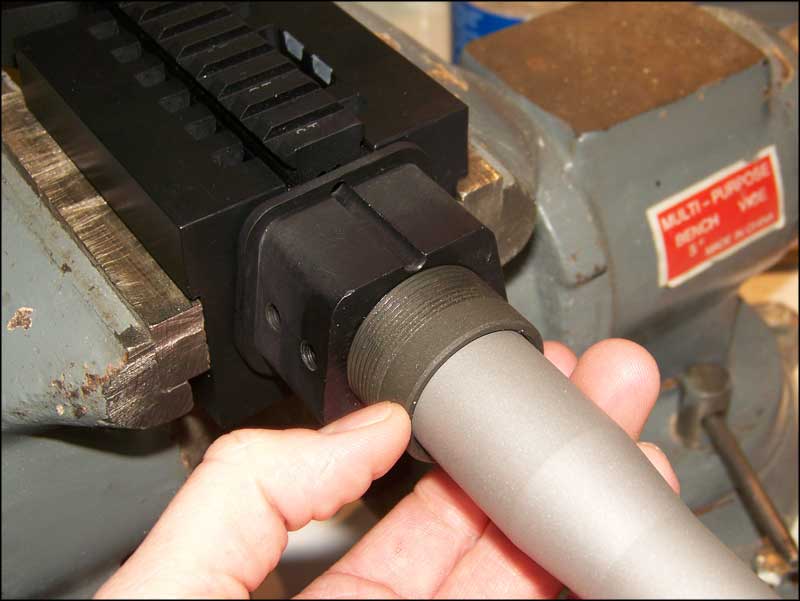
| Thread the mounting block onto the receiver. Turn it all the way onto the threads until it stops, then back it off until the gas tube hole lines up. | 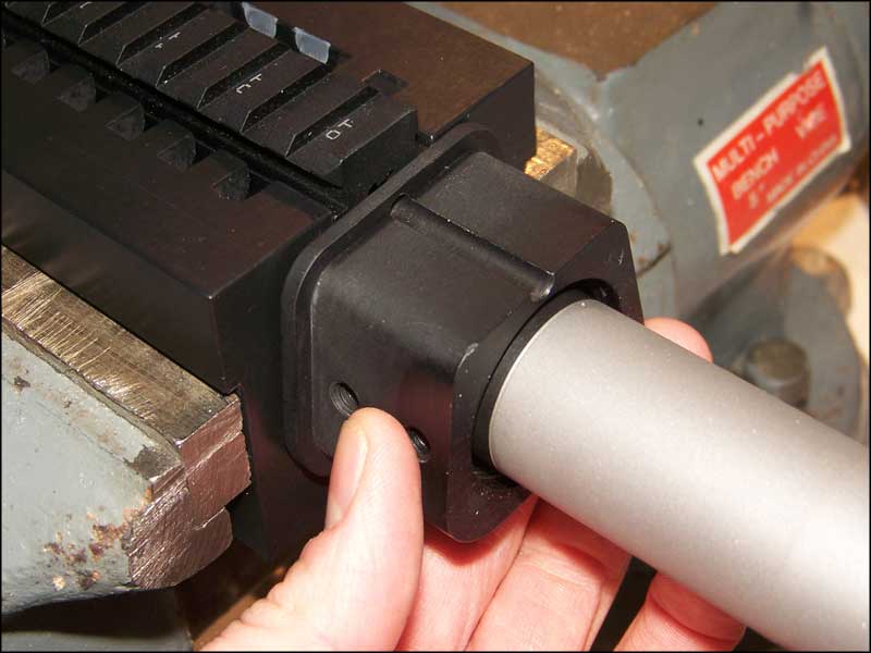
|
 |
Screw the barrel nut into the mounting block until it contacts the barrel shoulder. |
| Back off the mounting block and barrel nut 1/4 turn. Then turn the barrel nut back in to contact the barrel shoulder. | 
|
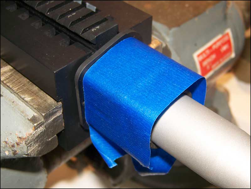 |
Wrap the mounting block with masking or riggers tape to protect the finish. |
With the adjustable wrench, tighten the mounting block until it lines up with the gas tube hole. Badger Ordinance recommends 35-60 ft. lbs. of torque. However with our setup we had to back off the mounting block and nut to 1/8 turn and tighten down to get within the desired torque. Getting an exact torque spec would require a 1 3/4" crow's foot and torque wrench. Common practice for barreling an AR is to tighten and loosen the nut 3 times then torque to final spec. Although this is not mentioned in the Badger Ordinance directions, we followed this procedure. |

|
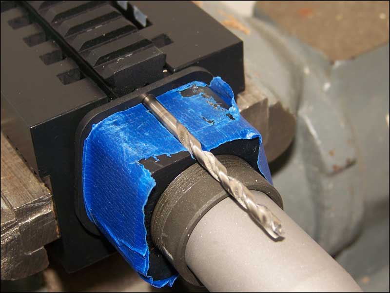 |
Use a 11/64th Drill Bit to confirm the alignment of the gas tube hole. |
| Place the tube on the mounting block. Then use a straight edge to check the alignment. Adjust as necessary. | 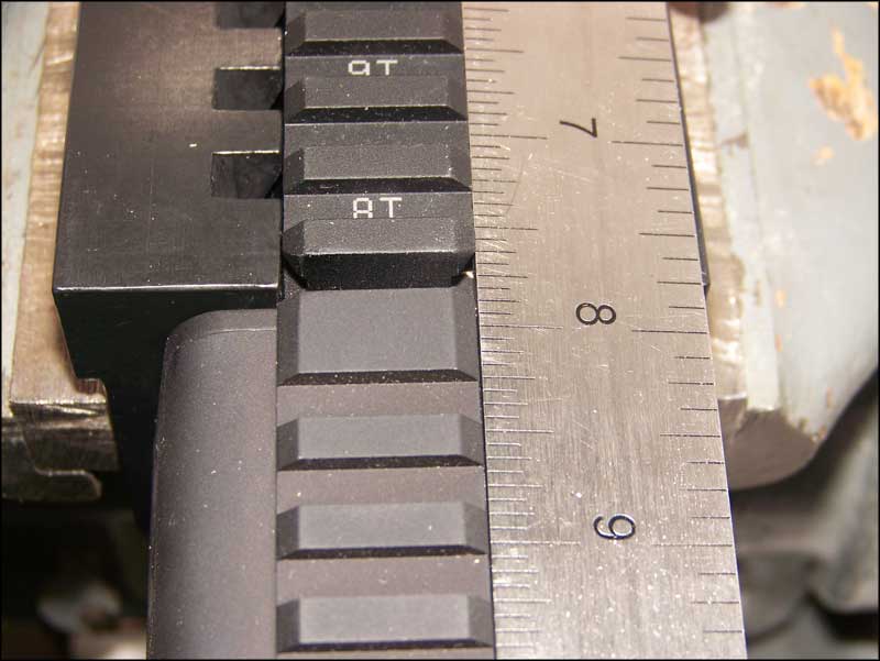
|
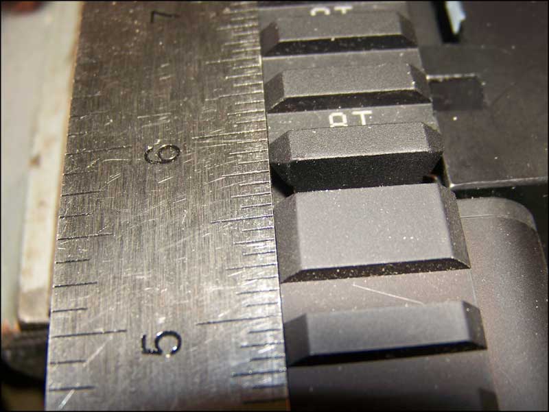 |
Here you can see proper alignment. There is no gap between the straight edge and the rails. |
| Heating the gas block will allow for it to slip into place more easily. We are not getting it red hot. Just hot enough to expand the block. | 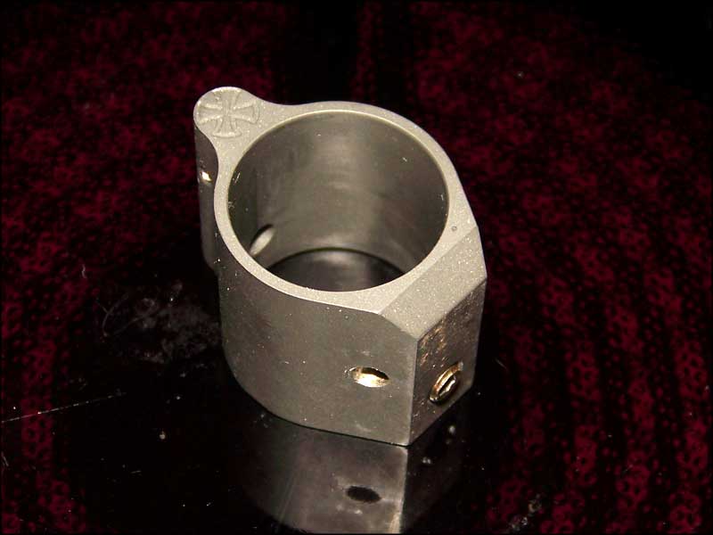
|
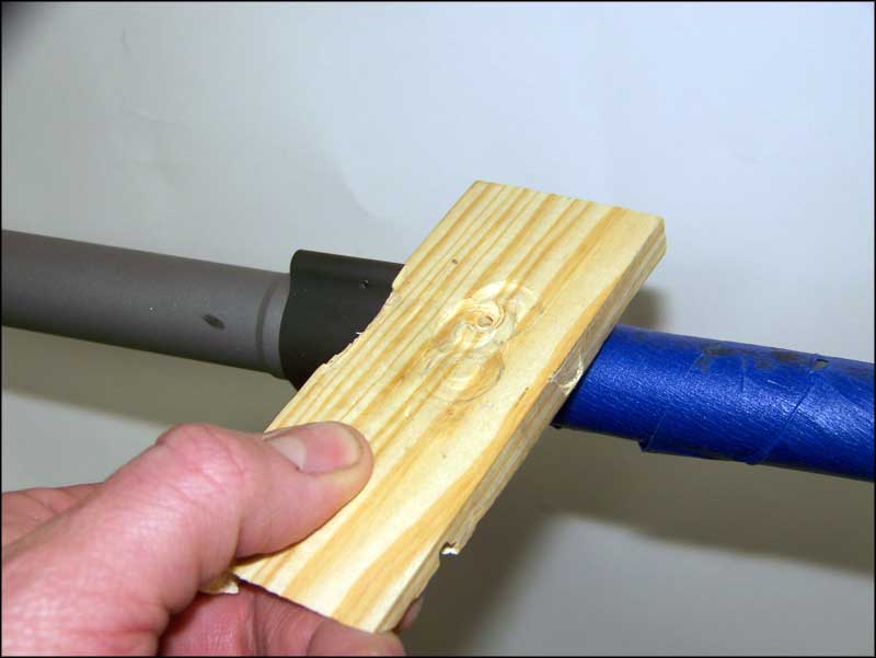 |
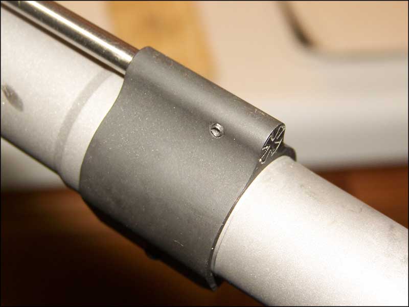
Seat the gas block in place. A wooden block and tapping with a hammer or mallet will help move the gas block into place. Notice the masking tape to protect the barrel from scuffs and scrapes. Tape the barrel after the block is slid on as far as possible by hand. |
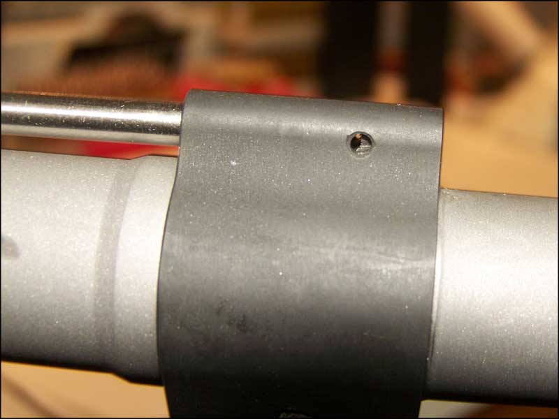
| Sight through the pin hole. If the gas block hole and barrel pin hole do not line up, use the mallet to tap the block until they do. | 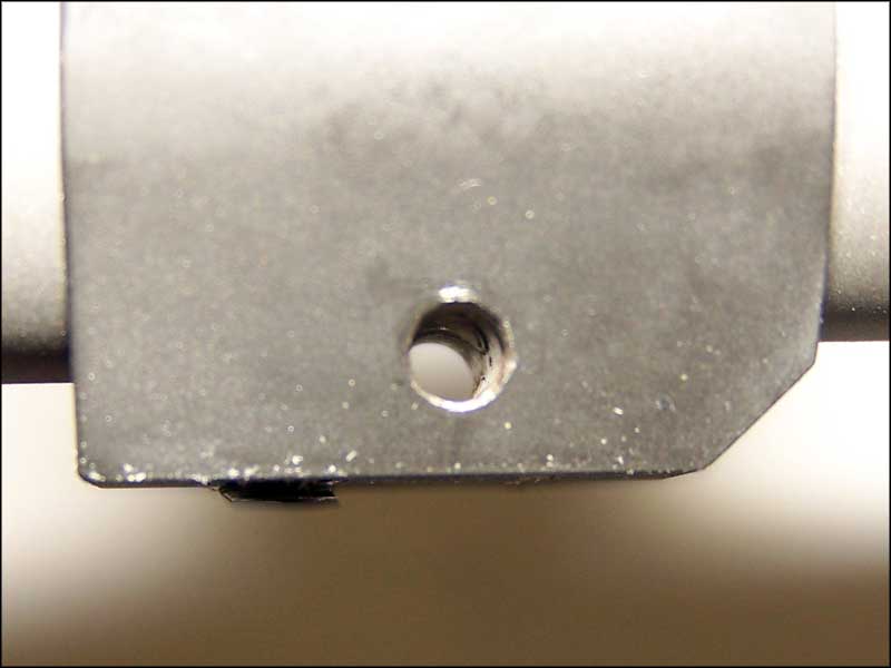
|
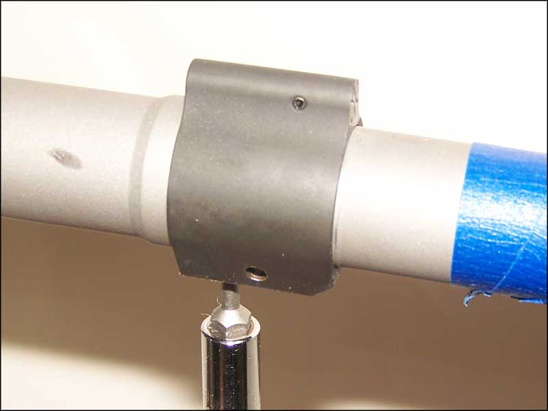 |
Install the set screw and tighten. |
| Notice that the mounting pin is chamfered on one end. This is the end to start into the hole. | 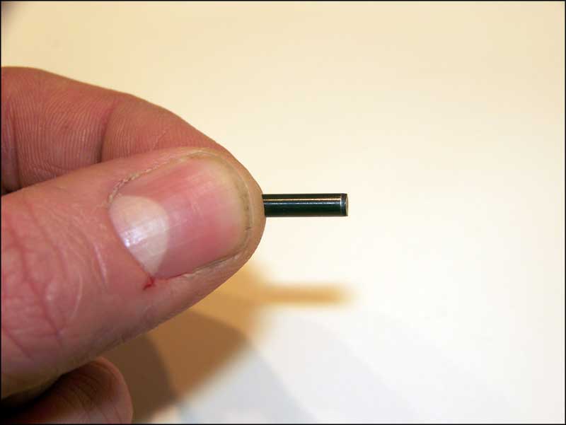
|
 |
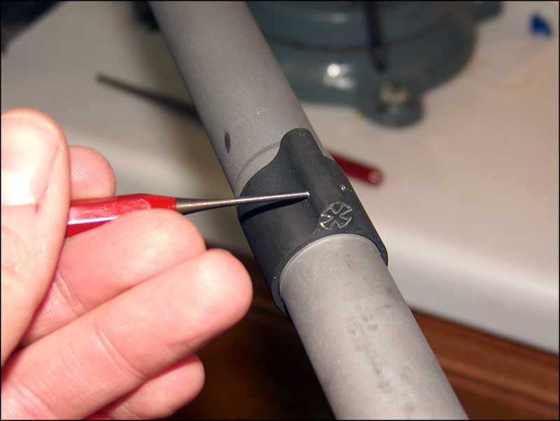
Secure the gas barrel in the vise by the gas block. Use cardboard or other padding to protect the finish. Tape over the side of the block around the pin hole to prevent scratching if the punch slips. Use an appropriately sized punch and drive in the pin. |
| The Pin does not need to be flush. Just drive it in until an equal amount protrudes from either side. | 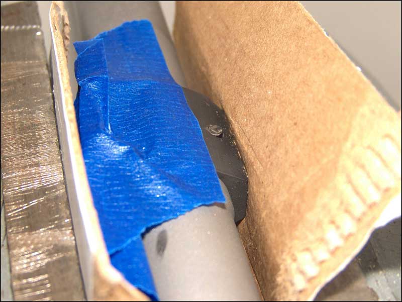
|
 |
For ease of handling I drop the barreled receiver back into the action block. |
| Tap out the gas tube retaining pin. | 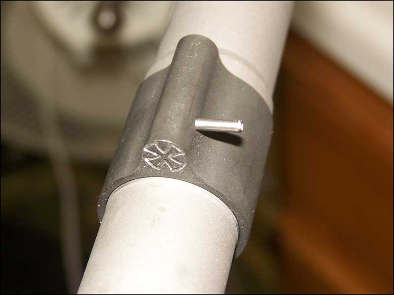
|
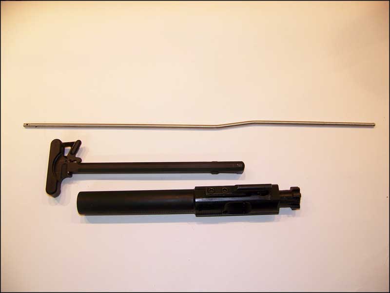 |
Locate your gas tube, charging handle and bolt carrier group. |
| Insert the gas tube into the hole in the mounting block. This will be the end without any cross-drilled holes. |
|
 |
Notice the orientation. Make sure the opening is on the bottom of the tube, and that the tube follows the contours of the barrel. If it contacts the barrel, you probably have it upside down. |
| Slide the tube into the receiver until you can line it up with the gas tube hole in the gas block. | 
|
 |
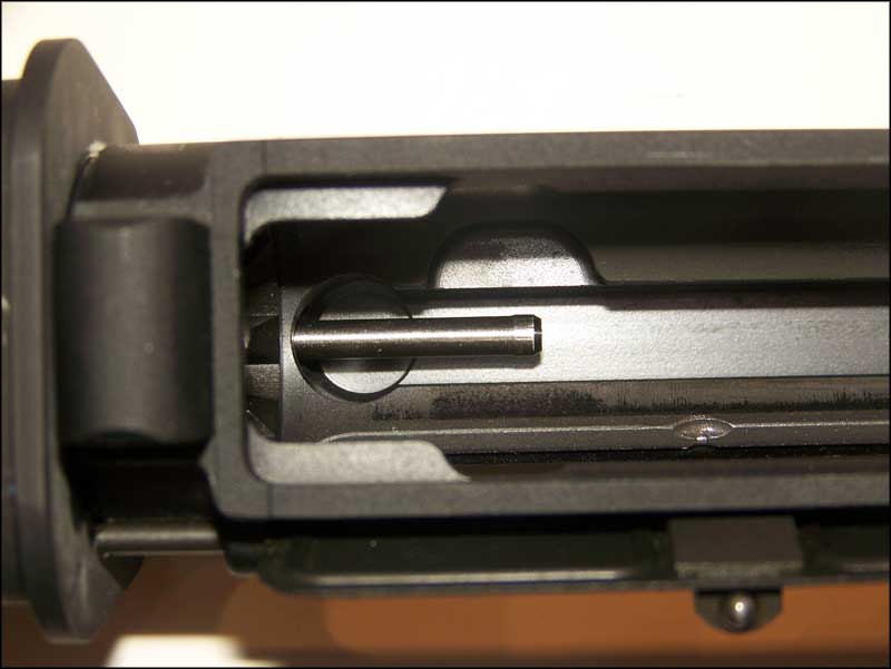
Slide the gas tube forward. |
| Notice that you can see the tube line up with the hole in the gas block. | 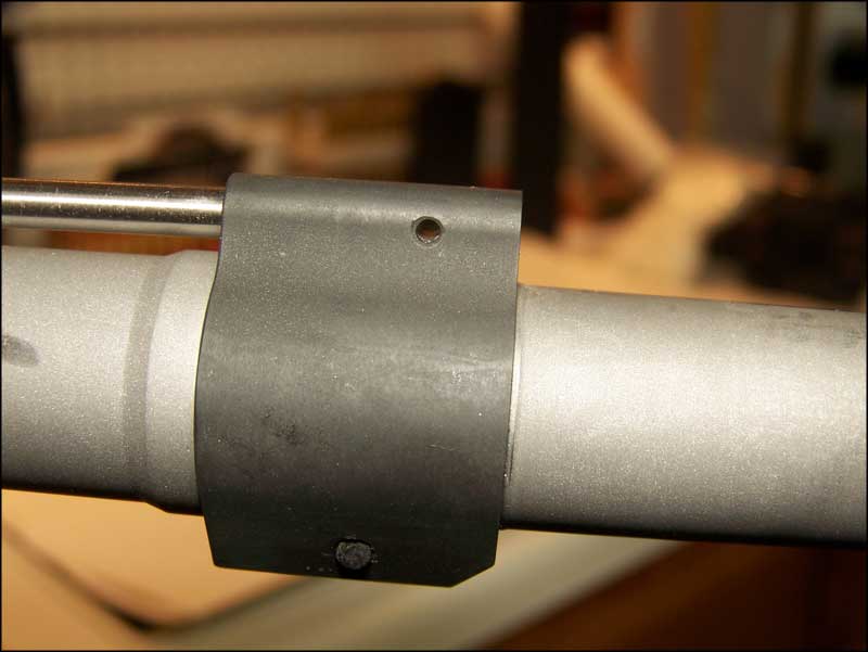
|
 |
Slip the punch through the hole to ensure everything is lined up. |
| Gently tap the gas tube retaining pin back into place. This is a roll pin, so it doesn't take much force. | 
|
 |
Make sure the pin is evenly centered in the block, left to right. |
Look through the receiver and make sure that the gas tube is not angled to one side or the other. If it is, first check to make sure the mounting block has not shifted and that it is centered. If the mounting block is centered but the tube is still angled then you may need to bend the tube ahead of the receiver slightly until its centered. If the tube is not centered it can be impacted by the bolt carrier gas key as the bolt reciprocates. This can cause malfunctions and possibly poor accuracy. |
|
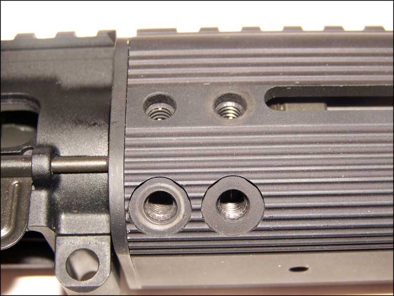 |
Now we are ready to install the tube. Slide the tube on and make sure the screw holes in the tube line up with the threaded holes in the mounting block. |
| Note that the screws are two different lengths. Four are short and four are long. | 
|
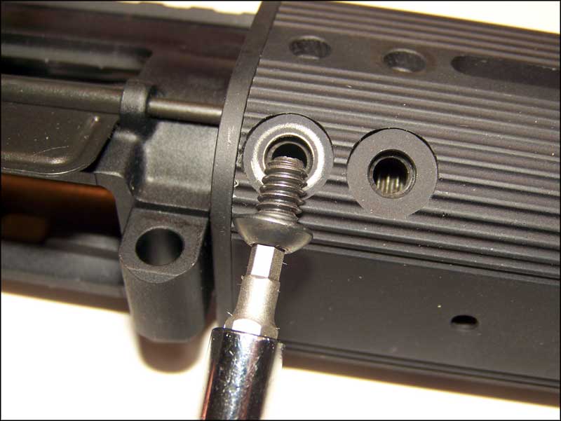 |
The long screws go into the lower holes on the tube. |
| The short screws go into the upper holes. | 
|
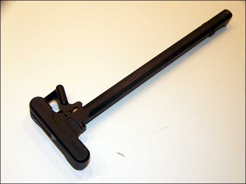 |
For this build we selected the PRI Gas Buster charging handle. This charging handle is designed to minimize the gas in the face of the shooter when firing the AR type systems. This is usually not a problem on a standard 20" rifle. It's worse on a shorter barrel or a rifle that is over-gassed. It is at it's peak on a suppressed rifle. After a day of training on my suppressed (non-Gas Buster equipped) M4 I usually have a black line of carbon across my right cheek. |
This rifle will eventually be suppressed, so it makes little sense to waste the money on a standard handle and replace it with a PRI later on. The Gas Buster also has the best extended latch I have used. It's comfortable for the shooter. Sure to grip, but does not hang out far enough to catch on gear. I am not a fan of the huge extended latch you see on many scoped rifles. They have a tendency to pull the bolt out of battery on rifles used in any kind of tactical shooting. The final step is to install your charging handle and bolt carrier group into the receiver and check for freedom of movement. Ensure that the carrier does not bind on the gas key. Once we finish assembly and adjustment I will cover checking headspace and function check. |

|
|
Coming Soon |
|